
What Is a Continuity Test?
A continuity test is an electrical check that determines whether a complete path exists between two points in a circuit. A meter sends a small test current through the path and measures the result. A continuous path usually indicates low resistance. An open path suggests a break, loose connection, failed component, or disconnected conductor.
Quick Facts About Continuity Test
Category
Electrical diagnostic test
Used for
Finding breaks in conductive paths
Common confusion
Continuity is not the same as voltage
Also called
Continuity Check, Circuit Continuity Test
Often discussed with
Electrical Troubleshooting
Key Takeaways About Continuity Test
- The test checks a path, not normal circuit operation.
- A low-resistance reading usually indicates a connected path.
- Continuity does not prove that a circuit is safe or correctly wired.
How Continuity Test Works
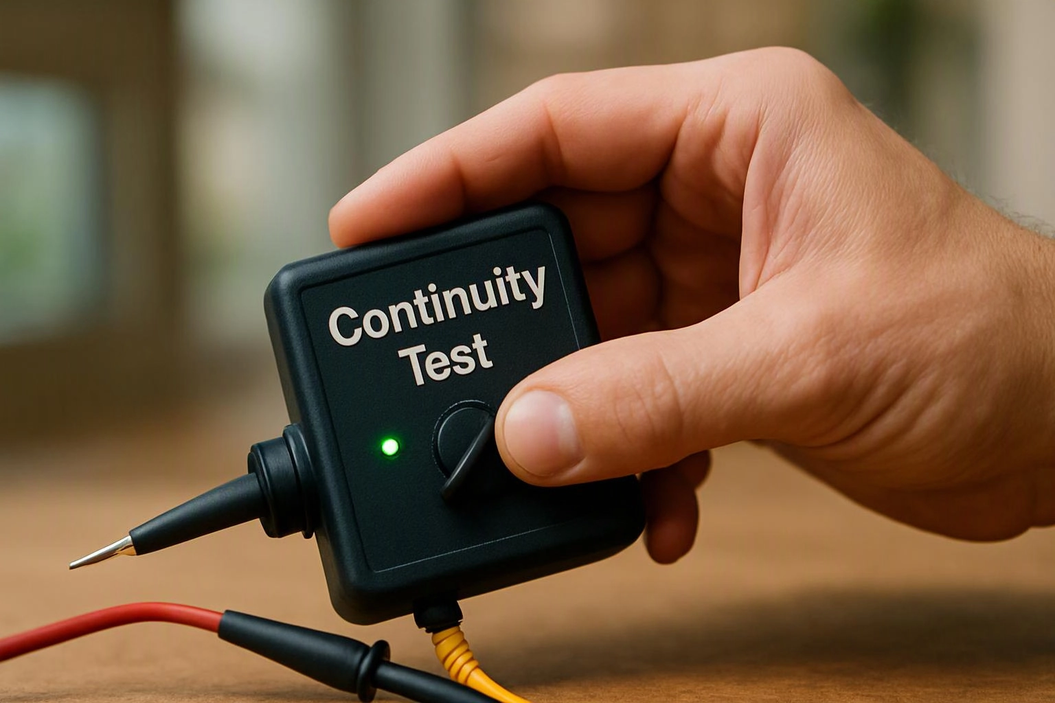
A continuity test checks the conductive path between selected points with a multimeter or similar tester. The instrument applies a small test signal and evaluates the path's resistance. A low-resistance result generally indicates that the points connect through wire, a switch, or another conductive component. A high-resistance or open result indicates that the path does not connect as expected.
Related glossary terms: Short Circuit, Electrical Grounding, Voltage Drop.
Technicians use continuity checks on de-energized circuits to trace conductors and inspect components. The test can reveal a broken wire inside insulation, a loose termination, or a switch that does not close. Continuity alone does not show whether the circuit has correct voltage, proper polarity, or adequate capacity. Those conditions require other electrical tests and visual checks.
Common Applications
- Checking a fuse or wire for an open path.
- Confirming that a switch opens and closes the intended circuit.
- Tracing conductors through a junction box or panel.
From the GMB Electric team
When we troubleshoot a circuit, we use continuity checks to trace suspected breaks and verify connections after isolating the circuit. We compare the meter result with the circuit layout and inspect terminals, splices, switches, and components. A continuity result guides diagnosis, but it does not replace voltage testing.
Continuity Test in Practice: A Real-World Example
A wall switch may appear connected while a loose terminal prevents the light circuit from operating. During Electrical Troubleshooting, a continuity test can check the switch and conductors separately to identify where the path opens.
Related Services
Related Terms
Short Circuit
A Short Circuit is an unintended electrical path with very low resistance between points at different…
Electrical Grounding
Electrical Grounding is the intentional connection of electrical equipment and systems to the earth through a…
Voltage Drop
Voltage Drop is the reduction in electrical potential that occurs as current travels through a conductor…
Wire Nut
Wire Nut is a twist-on connector that joins and insulates stripped electrical wires inside an electrical…
GMB Electric
Have Questions About Continuity Test?
Contact GMB Electric for practical guidance on Continuity Test and related 24 hour electrician work in Indianapolis.